Introduction |
|||
 |
A new amendment to BS 7671 (the UK wiring rules) was published on 15th April 2026, which has brought about significant changes to the electrical industry by including new technologies such as Secondary Stationary Batteries, clarification regarding services within protected escape routes, changes to medical locations and the inclusion of Power over Ethernet.
Industry practitioners have six months of grace period (which ends on 15th October 2026), where work can be conducted to either BS 7671 18th Edition Amendment 2 and 3 together OR to BS 7671 18th Edition Amendment 4. On 16th October 2026, only BS 7671 18th Edition Amendment 4 will be deemed as the current standard. Therefore, the clock is ticking on industry practitioners to demonstrate their competence. This article will cover a selection of top ten changes to the standard. |
||
The cover |
|||
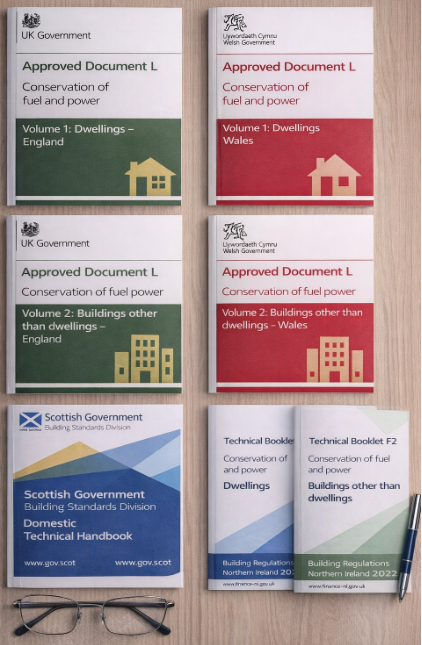
| Firstly the colour of the document has broken from the traditional cycle of RED, GREEN, YELLOW, BLUE BROWN, and the back to RED.
As BS7671:2018+A2(2022) had a BROWN coloured cover, the expectation was that Amendment 4 would revert back to RED. After deliberation in the committee it was seen to be more prudent to reserve the RED cover for new editions of the standard as opposed it being used for amendments to existing editions. As such, the decision was made to select a colour which harps back to a bygone age. ORANGE was last used in 1976 with the final variant of the Fourteenth Edition. So it is nice to see a revival of the bright orange or pumpkin coloured cover. |
|||
Part 2 – Definitions |
|||
| The inclusion of new sections and chapters within BS7671, brings new terminology, definitions, symbols, and abbreviations. This has expanded Part 2 of the standard. | |||
Part 3 – TN-C-S PNB Earthing Systems |
|||
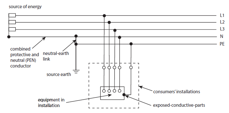
| A new earthing system has been added to BS 7671 (Figure 3.9B of Part 3). TN-C-S PNB (Protective Neutral Bonding) is not a new earthing system per se, however its appearance in BS7671 in the 18th edition amendment 4 makes it novel.
Unlike other earthing systems (with the exception of specialist IT earthing systems), PNB systems are not earthed at the source end. Instead due to the rural nature of such supplies, the source earth is generally located within 40m of the consumers installation (according to G12/4 engineering recommendations produced by the Energy Networks Association (ENA)), where an earth rod is driven into the general mass of Earth. The earth is derived from the neutral block where it connects to both a main earthing terminal to facilitate connection of the main earthing conductor for the consumers installation and the earth rod. |
|||
 |
|||
Figure 3.9B – TN-C-S PNB Earthing System, BS7671:2018+A4(2026) |
|||
| This system is not to be confused with a TT earthing system where the consumer is responsible for the consumer electrode. With TN-C-S PNB systems, the maintenance of the source earth (and the neutral-earth link) remains the responsibility of the DNO, i.e. the distributor and not the consumer.
So, if the responsibility for such an arrangement remains the responsibility of the distributor why is it important for electrical contractors to know? The main reasons are firstly to understand the maximum external earth loop impedance value to ensure that the consumers installation remains compliant as regards choice of protective device and levels of fault current to ensure quick disconnection of circuits in the event of a fault. Secondly, earthing system information impacts the design in relation to the presence of the Protective-Earth Neutral (PEN) conductor. With such (TN-C-S) systems larger levels of fault current exist in the in the neutral conductor under fault conditions. These need to be considered in order to not exceed the touch current limits of the installation which would pose a serious shock risk to users of the installation. Suitable protection for the system is then achieved by BS 7671 requiring larger cross-sectional area for equipotential bonding conductors when dealing with TN-C-S earthing systems than with other earthing systems such as TT or TN-S. The benefit for the electrical contractor is that due to extremely low risk of loss of PEN (or the neutral-earth link) in TN-C-S PNB systems due to this direct connection between the main earthing conductor and the source earth, some DNOs permit the equipotential bonding requirements associated with a TN-S system instead. Thus leading to a reduced cross sectional area of the equipotential bonding conductors and reduced copper usage, together with a faster simpler installation and lower material and labour costs overall. However, it is imperative for electrical contractors to double check the DNO requirements responsible for maintaining the network in the area of work, as some distributors may still require PME conditions to be satisfied. |
|||
Part 4 – 422 & Appendix 13 |
|||
| Section 422 that covers protected escape routes, has been re-written and now includes well defined areas of the built environment such as firefighting stairs, shafts, lobbies etc.. to guide designers on the type of electrical services and the relevant cable types that can be placed in such locations, in order to limit the impact to the fire loading of the building.
A protected escape route is defined as “A fire sterile, usually unpainted or carpeted – grey concrete part of the building where escape routes are maintained for people to reach places of ultimate safety.” Appendix 13 supports the regulations with Section 422 and provides general information on escape routes, information on the types of cables to be used and the final section tackles the topics of fire sealing and building penetrations. |
|||
Part 5 – 531.3.3 A53.2 |
|||
| Regulation 531.3.3 provides information on the types of RCDs.
As a reminder, there are four main types of RCDs recognised by BS 7671, each with its own set of characteristics and symbol. |
|||
|
|||
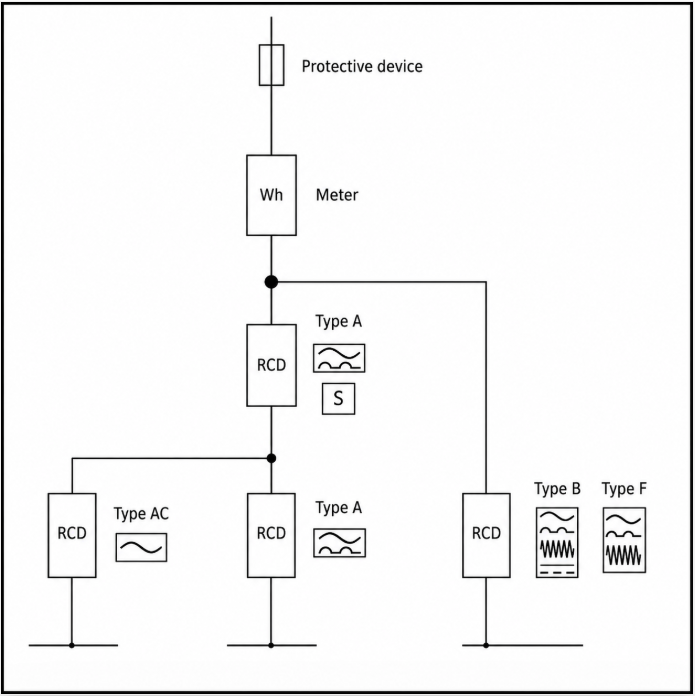
| Therefore the most capable device being a type B, followed by F, A and the least being type AC.
Figure A53.2 is a new figure added in Amd4 of BS 7671, which if considered, would ensure that upstream devices are protected against the effects of “blinding” in the presence of DC leakage or fault current. |
|||
 |
|||
Figure A53.2 Consideration of RCD types in series |
|||
| It shows the correct co-ordination of RCDs connected in series with the most capable device being furthest upstream.
Covering the figure (from left to right) we have: |
|||
|
|||
| The only time this would differ is if manufacturers of the devices permit the use of their less capable device upstream of their more capable device.
This can occur as through robust product development and testing, the manufacturer would be fully aware of the physical limitations of their device by analysing items such as the materials used within the RCD core, the internal arrangement of components and the various set points within software. The intimate knowledge of their product allows that deeper understanding of the pinch points and where RCD devices in series are at risk of DC blinding. Which, from a contractor’s perspective provides the assurance to follow the manufacturer’s instructions. The Tesla Training Team have produced other guidance on the topics of the different types of RCDs and the effects of DC blinding, which are well worth a read too. |
|||
| Different Types of RCDs – Tesla Technical Training LTD
Type AC RCDs and the effects of DC leakage current – Tesla Technical Training LTD |
|||
Part 5 – Section 545 |
|||
| Section 545 is a brand new section within BS 7671. It covers functional earthing and functional-equipotential bonding for information and communication technology (ICT) equipment and systems.
Datacentres are likely to be the next major global growth area as such BS7671 (influenced by work happening at international level) has brought this section into the standard with Amendment 4 to the 18th edition. It is important to understand that functional bonding is used for any reasons other than safety. Some specific items of equipment need functional bonding to prevent loss of data transmission or for noise reduction due to electromagnetic interference or capability (EMI/EMC). |
|||
Part 5 – 551.7.1 |
|||
| Regulation 551.7.1 covers additional requirements where generating sets may operate in parallel with the conventional supply. | |||
|
|||
Part 5 – Chapter 57 |
|||
 |
Chapter 57 is a brand new chapter within BS 7671 and covers the subject of stationary secondary batteries (sometimes called Battery storage systems). This is a major future growth area within the electrical industry and therefore specific safety requirements have been included in the standard.
Another resource which may be of interest is PAS 63100:2024. A PAS or Publicly available specifications are codes of practice for specific areas of interest that are commissioned by third party organisations. The BSI typically helps to facilitate PAS production and once completed, PAS documents become freely available resources for any interested stakeholders. In this case, PAS 63100 was sponsored by the Department of Energy Security and Net Zero and covers the topic of Electrical installations – Protection against fire of battery energy storage systems for use in dwellings – Specification. |
||
| PAS 63100 can be downloaded here;
https://www.bsigroup.com/siteassets/pdf/en/insights-and-media/insights/brochures/pas-63100-2024.pdf |
|||
Part 7 – Section 716 |
|||
| Section 716 is a brand-new section within BS 7671 which covers Power over Ethernet or PoE. | |||
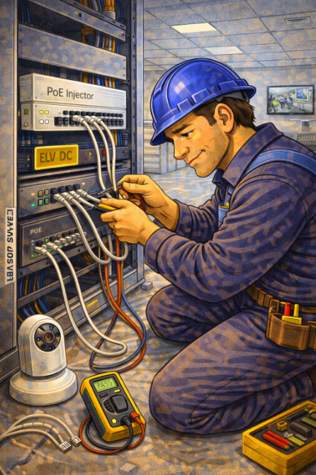 |
PoE is already an established part of the industry and permits the transmission of both power and data over an ethernet cable.
Application such as, smart security systems, CCTV, wireless access points, VoIP phones, and the whole push of Internet of Things –controls for lighting, HVAC, access control, environmental sensors, public signage as common-place use cases. BS 7671 permits the use of ethernet cable to DC power of up to 750 mA over an ethernet cable. There are different categories of ethernet cables, each with properties including the speed of data transmission and bandwidth including;
Therefore it is nice to see PoE and Section 716 in BS7671. |
||
Part 8 – Chapter 81 |
|||
 |
A new Chapter 81 has been introduced to BS 7671 18th edition Amendment 4, to reflect the landscape related to UK legislation within this area of energy efficiency.
|
||
| Chapter 81 and the UK legislation described above takes precedence over BS HD 60364-8-1:2019 covering Low-voltage electrical installations. Functional aspects. Energy Efficiency is an available standard in the UK.
However, as this Harmonised Document provides additional requirements, measures and recommendations for the design, erection, operation, and verification of all types of low voltage electrical installation including local production and storage of energy for optimizing the overall efficient use of electricity. Designers may therefore find it helpful to supplement the advice given in Chapter 81 with additional information as outlined in BS HD 60364-8-1. |
|||
Conclusion |
|||
| This article covers ten of the major changes to BS 7671 18th Edition inc. Amendment 4 however it still just scratches the surface.
A deeper dive into the changes is required to answer questions such as; |
|||
|
|||
| Tesla Technical Training have therefore produced one of the most comprehensive courses covering the changes to BS 7671 18th edition Amendment 4. | |||
| BS 7671:2018+A4 (2026) Requirements for Electrical Installations, IET Wiring Regulations – 18th Edition Incorporating Amendment 4 – Updates Course | Tesla Technical Training Ltd | |||
| This training course has the eFixx seal of approval and is worth 6 hours of CPD.
Complete the training now (by visiting the link above) in readiness to prove competence at your next annual Competent Person Scheme (CPS) audit OR simply to understand the changes and, more importantly, how they impact you and your business. |
|||
| “if you know more than when you first started – it was a worthwhile endeavour!” | |||
C&G Exam |
|||
| If learners desire, there is the option to book a City & Guilds examination at the following link: 18th Edition | Tesla Technical Training Ltd
The remote option is fully organized by City and Guilds invigilators who, once booked through our website, will be in touch to confirm a convenient date and time for your exam. Please note, the examination consists of 60 questions and covers the entire book (not just the changes with Amendment 4). The duration is 2 hours, and you must achieve 36 correct answers out of 60 ( or 60%) to pass the assessment. |
|||
| We hope you enjoyed reading short article and hope to see you on our course soon…. | |||
 |
|||